Gardening Robot
August 2024 - April 2025
TLDR:
Designed a 3 DOF, 1x1x1 meter CNC machine to support a claw arm, basing the design on hobby CNC machines and utilizing as many spare parts as possible, leading to successful operation of the robot while staying 20% under budget
Designed and built a rack & pinion actuator for the vertical joint on the CNC using a high-torque stepper motor and a keyed pinion gear, leading to successful lifting of 70 lbs, 40% higher than the minimum designed for.
Programmed actuation/control script for 6 stepper motors on an Arduino, enabling control of the robot and ensuring seamless connection with our ROS architecture
Led the design and fabrication of a small, low-fidelity prototype of the robot, utilizing spare parts and 3D printed rack and pinion mechanisms, quickly enabling development of the computational side of the project.
My capstone project for my final year of my undergrad degree was to make an autonomous gardening robot. The inspiration for the project came from research on the ‘Three Sisters’ which is a method of growing corn, squash, and beans, all in the same space to take advantage of their symbiotic needs.
Research:
We began by researching current technologies in the area and by interviewing professors knowledgeable about robotics or horticulture. Through our research we found that there are existing robots that can plant seeds, water gardens, and even prune plants and weed-whack. However, there was no robot that was able to harvest fruits. We decided that, due to time constraints and the potential novelty of our work, to prioritize developing harvesting capabilities for plants such as corn and squash.
I led the brainstorming of what our design would be, by having us all come up with whatever random ideas we had on sticky notes and then ranking them all together afterwards. We settled on a design utilizing a CNC-like machine that would span an entire crop bed, like a claw machine. Attached to this would be a 3 DOF robotic arm with a gripping tool attached as an end-effector (Imagine like your arm - the robotic arm has a shoulder, elbow, and wrist, and hand). The robot would operate semi-automatically, using computer vision to detect where plants and fruits were and using path-generating algorithms to navigate the tool to the desired location.
First Prototype:
Our design’s autonomous nature meant that our computer science teammate would have a lot of work to do. Obviously, a working mechanized prototype would be needed to develop and test the path planning and object detection. I led the team to quickly develop a prototype that would work just well enough to develop the computational side of things, no matter how shoddy. This included 3D printing rack and pinion mechanisms for linear actuation and wiring an Arduino up with motor controllers for 3 steppers and 3 servos.
Final Prototype:
At the start of the spring semester we began working on our final prototype. This prototype would be 1x1x1 meters in size, higher-fidelity, and designed to actually be able to cut an ear of corn (a prop, not a real one) and transport it to a collection box.
I designed the structure of the robot. Given that we would expect the robot to be deployed in the field, metal was the only option for the material. Given the cost effectiveness, I chose to use exclusively aluminum extrusions as the structural materials, used leftover aluminum plates as brackets in each joint, and used castor wheels (to roll along in the groove of the extrusions) instead of expensive linear rails, which all saved us around $2,000.
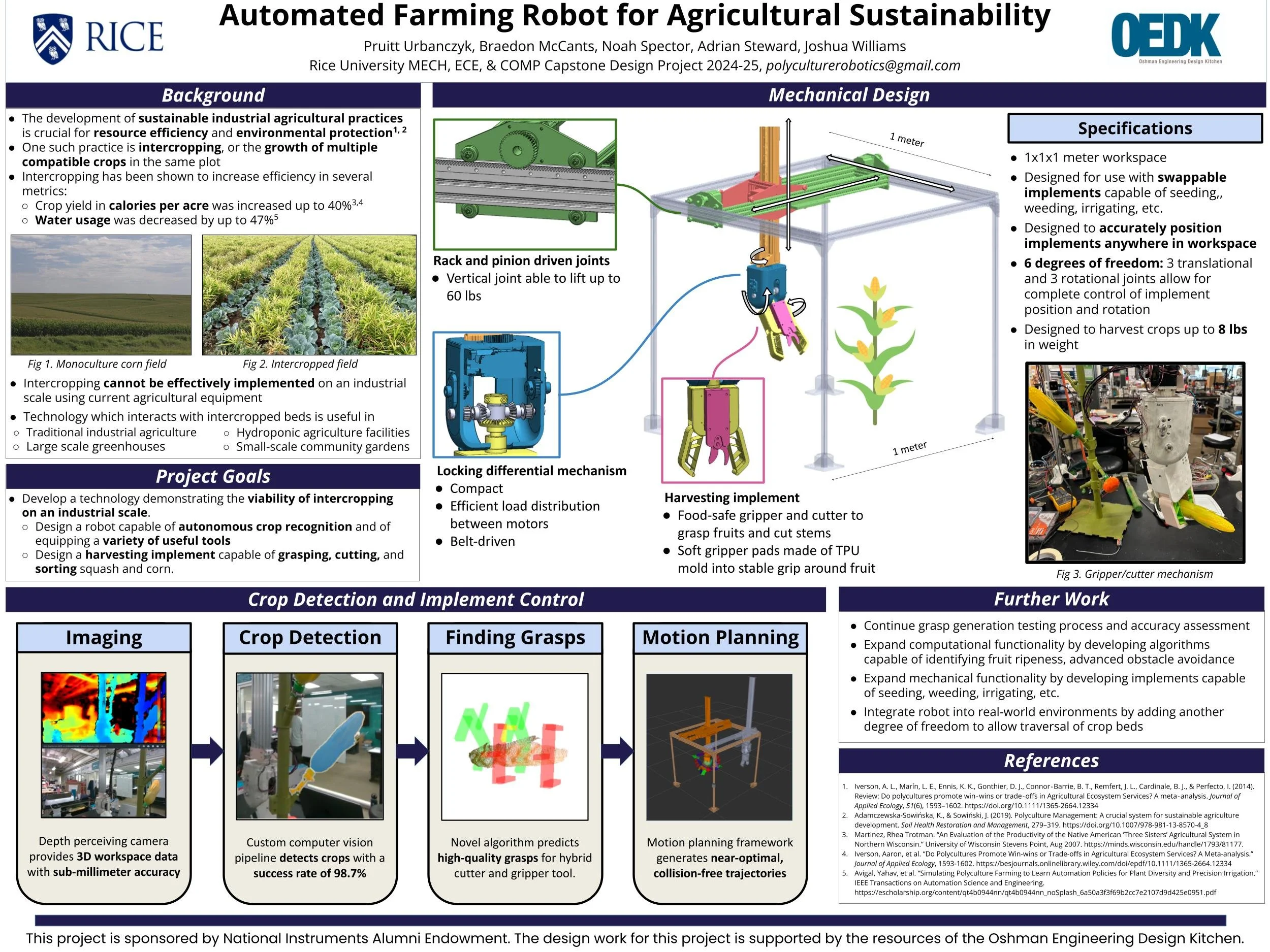
Although I believe that using a leadscrew would have been a better solution for the linear actuation, due to cost constraints I decided to use rack-and-pinions for each joint as I was able to find over 3 meters of identical geared racks and a two gears of the same pitch. This left only a handful of hardware left to purchase.
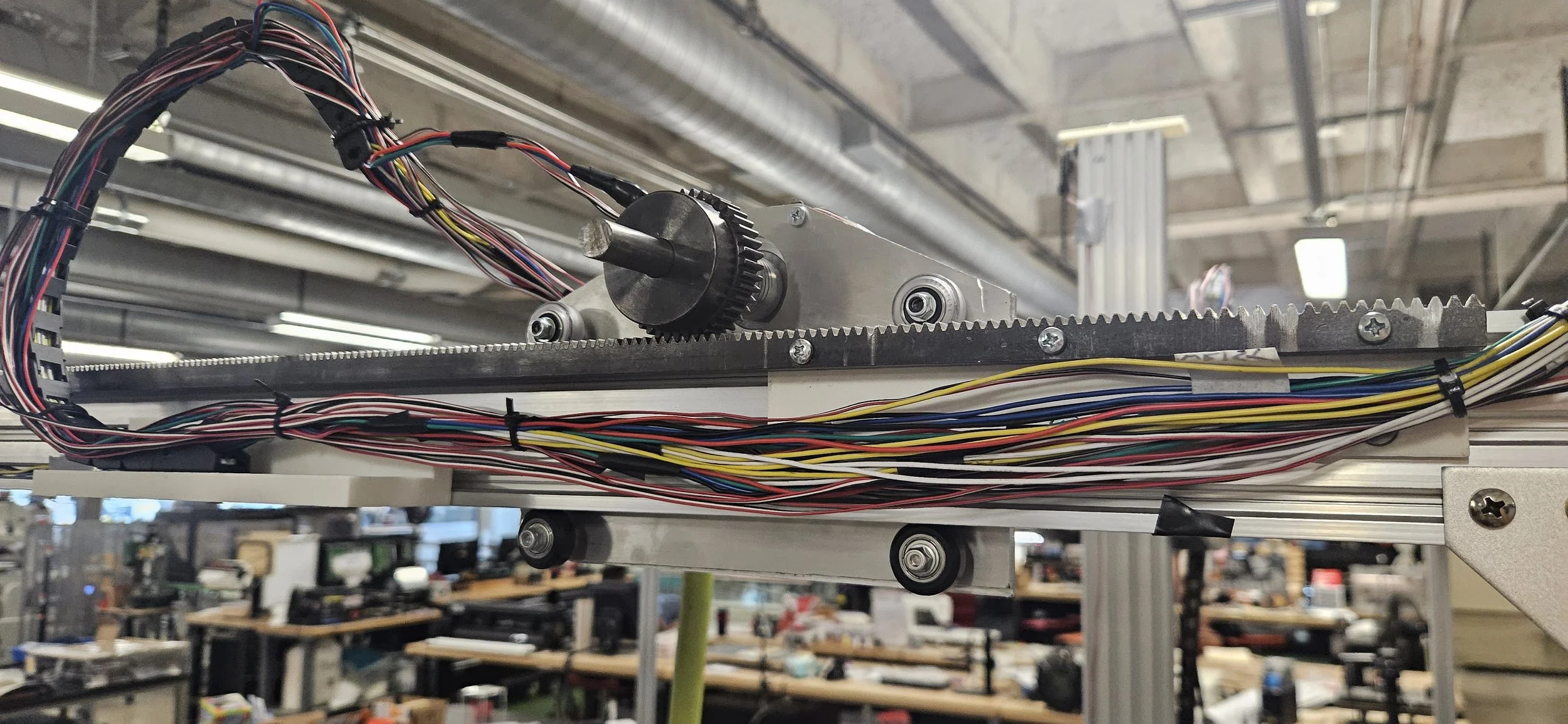
Given that the vertical joint needed to use a rack-and-pinion mechanism instead of a leadscrew, I had to design a linear actuator from scratch. I modified the shaft of a NEMA 34 motor so that I could attach a keyed gear, to keep up with the required torque. Additionally, I decided to use a special type of extrusion for the body, shaped like a ‘C’, allowing for the driven rack to be mounted in the cavity so that its in the same plane with the castor wheel guides. I tested its lifting capacity and it was able to lift up to 70 pounds, 40% above the minimum designed for.
Actuation & Integration:
The team was having trouble getting the our stepper motors and servos running properly. I have a lot of experience with Arduino so I took the responsibility of getting them to work properly although the task wasn’t originally assigned to me. I utilized a root-cause analysis to troubleshoot the issues, which ended up being that the motors weren’t getting enough current and that the programming on the Arduino was faulty. We ordered a new power supply to fix the current issues and I rewrote the program, allowing perfect interfacing with our ROS architecture.
Reflection:
In the end, the robot was able to function properly, but we cut our time too close and didn’t give our computer science teammate enough time to completely finish his work on the final prototype. The robot was able to teleoperate and do anything manually, but the autonomous harvesting didn’t get finished.
To be fair to him though, he had a very hard job and I think he would be able to write a proper research paper on what he did with so little time. I think that given our time constraints and our budget, we did an incredible job.
I think that my design of the structure could have been better. It ended up having a lot of vibration due to the thin legs, lack of smooth motion control (which we had to abandon last-minute due to the requirements of the path-planning algorithm), and the use of flexible shaft collars on the motors (which were the only ones we could find to fit our specs). Looking back I would’ve changed the design to be more rigid, maybe by using plastic parts to reinforce the structure.
In addition we we vastly underestimated how much of a problem wiring would be. We had to scrap our original plan last minute and ended up having to just do what would work, even if it is a bit of an eyesore.

First prototype, quickly thrown together to let the computational aspects to be developed as a higher fidelity prototype is designed
Full operation of the robot
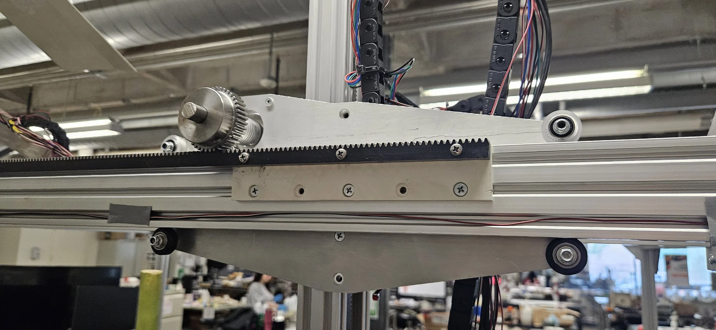
Horizontal joints of the robot using rack-and-pinion mechanisms
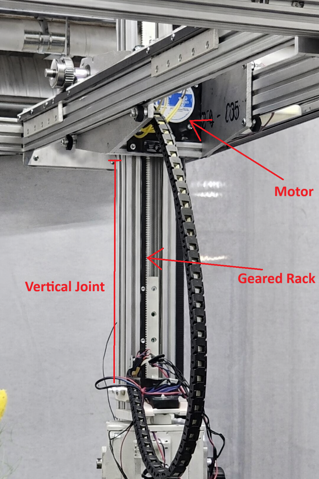
Vertical joint: Left image is the view of the ‘parent’ half, with the motor, pinion, and guide wheels.
Right image: view of the ‘child’ half, including the geared rack and the structural component.
Full operation of the 1st prototype