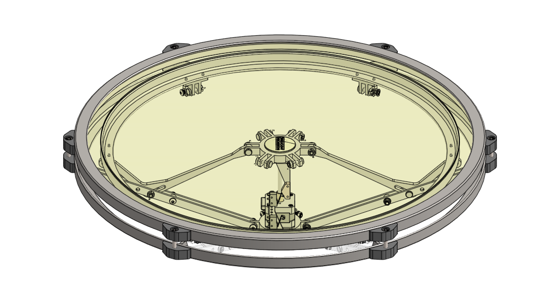
CAD Model of the newest prototype. The redesigned bearing surface mount is in grey, near the center of the image.
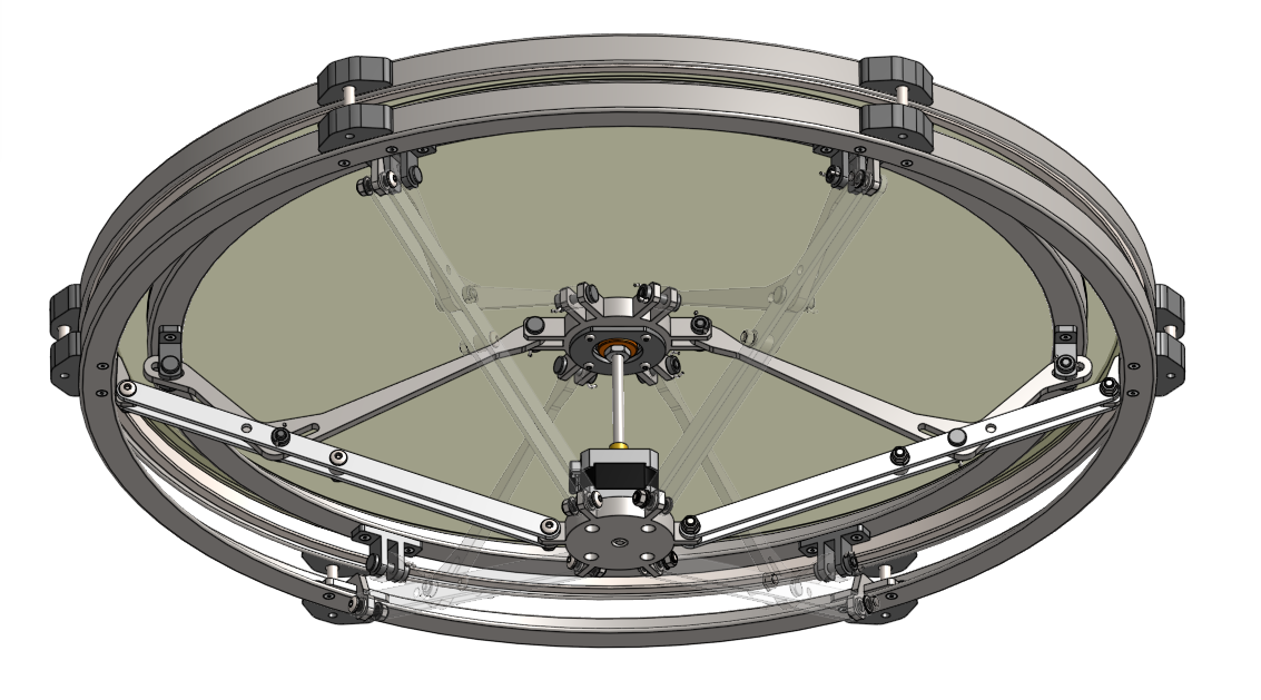
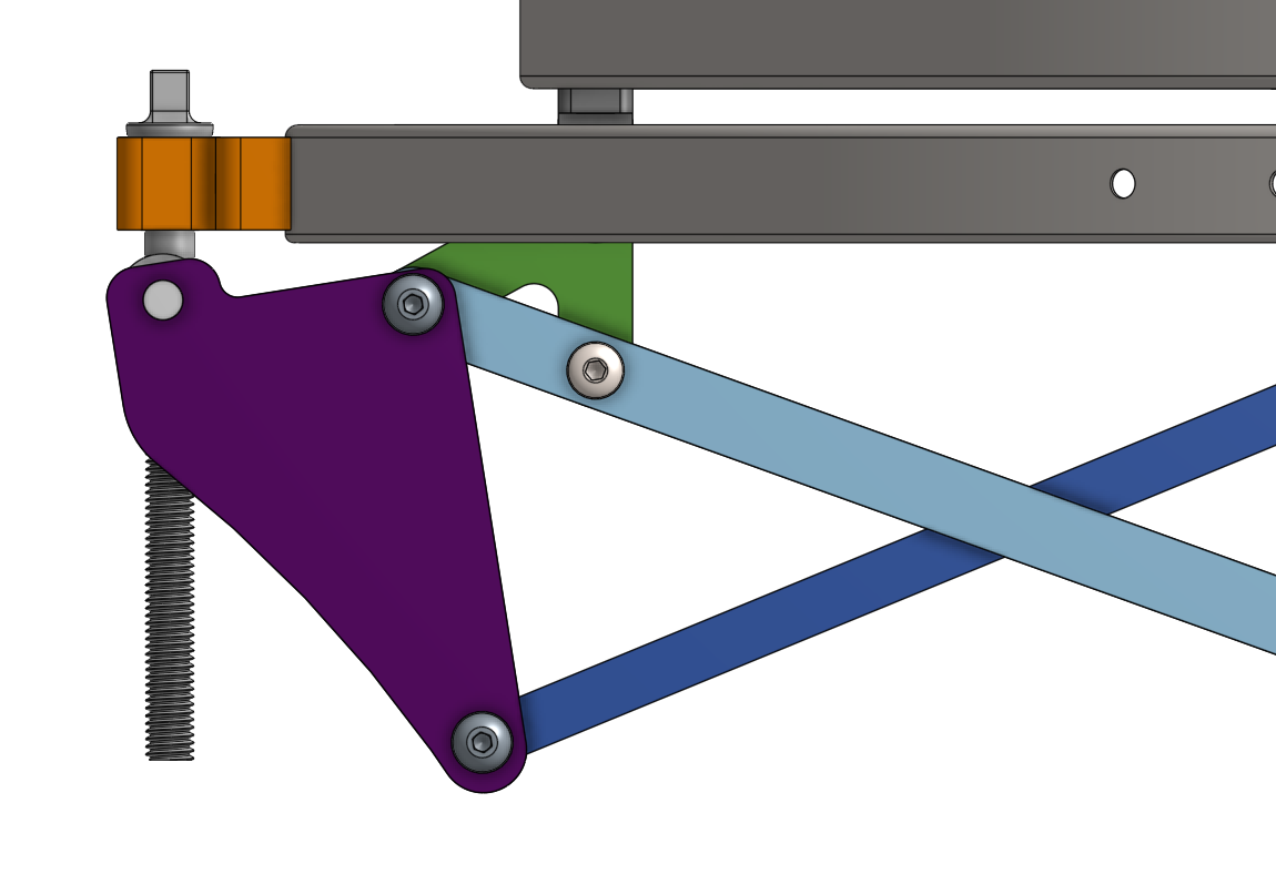
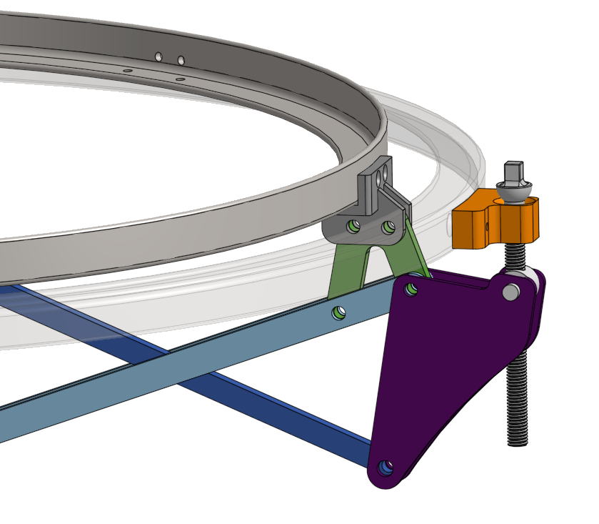
CAD model of the second prototype. The bellcrank is visible in purple. As the stepper motor moves the nut on the lead screw, the dark blue arm pulls the bellcrank which pulls down the head.
Bringing the second prototype through the full tuning range. Notice the bending as the tension rises.
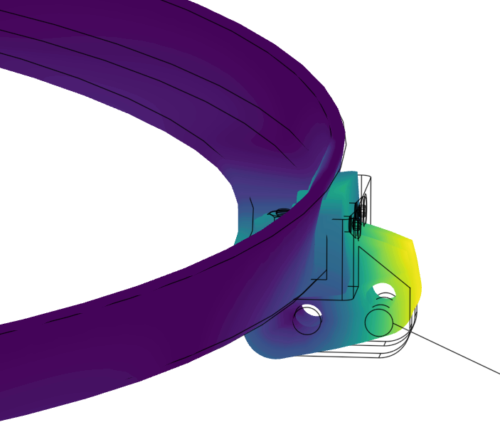
FEA of the redesigned bearing surface mount. Displacement is heavily exaggerated.
This section is under construction and may be missing some details. Feel free to see my other projects here.
TLDR:
● Designed a mechanical system allowing for a stepper motor to change the tuning on a timpani drum, allowing for a prototype to successfully reach the entire tuning range
● Troubleshooted structural deflection in the drum utilizing a root-cause analysis and FEA to redesign certain parts to better handle applied load, successfully eliminating the failure mode
● Devised a method to estimate tensioning bolt force by correlating motor torque with structural deflection observed in an early prototype, then validated and refined the approach using FEA to improve measurement accuracy
This is an ongoing project to create a timpani drum that can tune automatically. If you’re not familiar, timpani are a type of drum that can be tuned quickly, usually being controlled with a foot pedal. However, many timpanists find themselves needing to use up to 5 differently sized timpani at a time, leading to a juggle that can become disorienting. With timpani that can tune automatically, the notes for any song could be programmed automatically - all the timpanist would need to do is hit the drum at the right time.
This is a personal project of my boss Keith, which I have been working on outside of my employment responsibilities. I’m not a percussionist myself, but I got pulled into the project because I found the problem to be mechanically interesting, and I’ve been working on it since.
A broken prototype:
A drum is a very simple device - you have a drum head and you have a bearing surface. Usually, the head is pulled down onto the bearing surface. This creates tension in the head - which is what controls the pitch of the drum’s note. Higher tension = higher pitch.
The original idea for this project was to use a motor with a lead screw to push the drum’s bearing surface into the drum head to achieve tension. This was fully designed, built, and tested - and it failed spectacularly. The arms holding up the bearing surface couldn’t handle the stress and they snapped. So, Keith was looking for some fresh eyes on the project and had me take a look.
I suggested that instead it would be smarter to try a more conventional approach first - let’s use a motor to pull the head down instead of pushing the bearing surface up. That way, we could verify that this was even reasonably possible without trying to reinvent the wheel. In addition, this allows for the use of a bellcrank - a type of crank mechanism that can be used as a lever in tight spaces - which would mean a weaker motor could be used.
I pitched my idea for a new design and Keith liked it - but since I went on a long offshore trip a few days later he had someone else bring the design to manufacture and testing. When I returned, the new second prototype was functioning, but it wasn’t reaching the full tuning range. Neither Keith nor the person who built and tested the drum could wrap their heads around why it wasn’t working. So, I took the initiative to get to the bottom of the issue.
Research:
I spent a few days after work taking a lot of measurements of the timpani to verify that the prototype matched the design. I wanted to see what the difference was between our perfect CAD model and the real prototype. Everything matched except for the difference in height between the bearing surface and the head’s retaining ring. The design was made so it would reach a maximum of 9mm, but it was only reaching about 4mm, meaning that the head wasn’t being tensioned enough.
After that, I noticed a few more concerning things. Many of the bolts on the bearing surface were extremely bent. The bearing surface itself was heavily warped. The 6 bolts connecting the head to the bell cranks were bent as well. Simply put, the prototype couldn’t support its own strength.
There were a lot of things wrong with this prototype, but I determined that by fixing only one of them we could make the prototype work. As the prototype went through the tuning range, you could notice the supporting arms, which are supposed to be fixed, (in light blue) slowly rise. Following these was the bearing surface, which was the root cause for the incorrect height difference. By redesigning the mounts for the bearing surface, I believed I could fix this problem.
Redesign:
I started by estimating the actual tension in the head we needed to apply. We were unable to measure this in more conventional means, such as strain-gauged bolts or measuring bolt elongation due to cost and size. I ended up estimating it with a few different non-conventional methods to hopefully converge on something reasonably accurate.
First, I used the warped bearing surface. I noticed how it would flatten while the prototype was at it’s maximum tension, so I measured how much weight I could put on it until it flattened perfectly. This ended up being around 200 lbf, giving us a lower bound for the required tension.
Second, I found an equation relating vibrational nodes of a circular membrane to the applied tension, which suggested a max tension of around 250 lbf. I did have to estimate a few physical properties of the head, though.
Third, I used a torque wrench on a few conventional timpani to roughly estimate how the head bolts were loaded. This averaged out to around 400 lbf on some noticeably unlubricated bolts. I considered this to be the upper bound.
Considering a factor of safety, I redesigned the bearing surface mounts using 400lbf as the target tension needed. I utilized FEA analyses of the part to verify that it could handle the stress. After assembling the new third prototype, the timpani had no problem reaching the full tuning range.
Moving forward, I am currently working on a new design to return to the original idea of the first prototype, where the bearing surface is pushed up into the drum head. This is what Keith wants, as it would be much easier to store and transport.
The first prototype that didn’t work. Left = top view, right = underside view.
